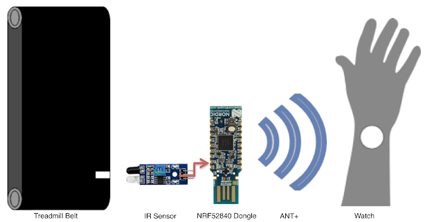
The Concept
From a conceptual level here's how things work. As the treadmill belt rotates around a white mark on the belt is seen by the infrared (IR) sensor. The IR sensor signals to the NRF52840 Dongle (dev board) that the mark was seen. The dev board knows the length of the belt so it's able to calculate total distance traveled and instantaneous speed. The dev board then sends that information wirelessly to the watch using ANT+ and the ANT+ Stride-based Speed and Distance Monitor (SDM) Profile.
In later posts I'll talk about what goes how the data is calculated and more about ANT+ and the SDM profile. But for now let's look at the physical connection between these two boards.
The Connections
Power
 The NRF52840 SOC is capable of providing regulated power through the VDD pin from 1.8 to 3.3V. This is good news, because the IR sensor will run on 3 to 5V. Even better, the nRF SDK examples using the NRF52840 Dongle already take care of setting up the configuration to set VDD to 3.3V. But if you're in doubt, use the multimeter to measure the voltage between VDD and GND.
VDD on the NRF52840 Dongle connects to VCC on the IR Sensor.
Ground
There are a few ground pads on the NRF52840 Dongle. The easiest one to use is pad next to VDD. This way if you like to solder header pins on for a 3-wire Dupont connector, the pins can all be next to each other.
GND on the NRF52840 Dongle connects to GND on the IR Sensor.
Signal
There are 15 GPIO pins brought out to the edges of the NRF52840 Dongle. Any of these will work, but 0.31 is right next to the GND pad that was right next to VDD. So this seemed like a good choice since I was planning on soldering on header pins connect the two boards with a cable instead of directly soldering them.
0.31 on the NRF52840 Dongle connects to OUT on the IR Sensor.
How Does it Work?
The IR Sensor works by shining an infrared (IR) LED and looking for its reflection. Black surfaces (a treadmill belt, for instance) tend to absorb most of this light providing very little reflection. White surfaces, on the other hand, reflect most of this light. On the IR Sensor is an adjustable potentiometer to dial in the sensitivity to a desired level.
The IR Sensor outputs a voltage roughly equal to the VCC input voltage provided to it when there is not a detection. Since we provide 3.3V as input, the Signal line sits around 3.3V when the treadmill belt is seen.
When the IR Sensor detects an "obstacle", a white mark on the belt in our case, the Signal line goes to roughly 0V.
When it's time to start programming the code to handle our events, we'll be looking for events where the Signal line drops from 3.3V to 0V, or a high-to-low transition.


Comments
Post a Comment